


News
- ▶ How alloy wire diameter tolerance affects automated forming accuracy
- ▶ When alloy wire is the right choice for high-temperature heating elements
- ▶ How to prevent coil damage during delivery from a Monel 400 supplier
- ▶ How to compare freight costs from a monel 400 Coil supplier
- ▶ How coil edge quality affects stamping with Monel 400
Message
How alloy wire diameter tolerance affects automated forming accuracy
Automated forming does not respond to a nominal wire diameter; it responds to the actual diameter entering the feed rollers, guides, dies, and bending tools at that moment. When Alloy Wire varies beyond the tolerance assumed during setup, the machine may still run, but feed length, bend angle, springback, and tool loading can drift. That is how apparently small dimensional variation becomes a repeatability, quality, and, in some applications, safety issue.
The practical question is not whether a diameter tolerance exists. Every wire specification has one. The question is whether the permitted variation is compatible with the forming process, the alloy condition, and the functional tolerance of the finished part. A tolerance that is workable for a simple open bend may be unacceptable for a tightly wound spring, a formed retention clip, or a high-cycle component.
Why diameter changes affect a forming line
Wire diameter influences both the amount of material moved through the machine and the force needed to deform it. A slightly oversized section has a larger cross-sectional area, so it resists bending more strongly. A slightly undersized section bends more easily and can pass through feed equipment differently. In automated equipment, those effects are amplified because the setup is fixed while the material changes.
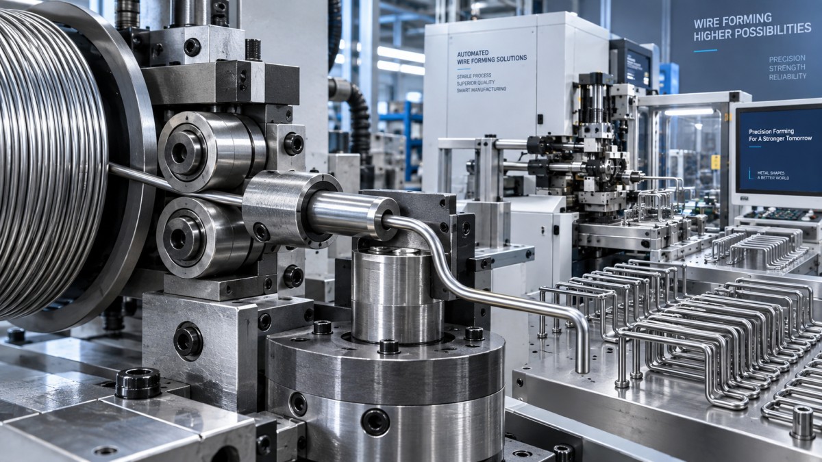
Feed rollers are a common starting point. Their pressure is selected to grip the wire without marking or flattening it. If the incoming wire is larger than expected, roller pressure rises and may create surface damage, excessive drag, or distortion. If it is smaller, the rollers may slip. A feed encoder can then record roller movement rather than true material movement, producing incorrect cut lengths or misplaced bends.
Diameter also affects the wire-to-tool relationship. Guides and straighteners have limited clearance. Variation can change how centrally the wire enters the die, particularly where the machine uses several guide points before a tight bend. Off-center entry raises the chance of asymmetric bends, scratches, local scoring, and unstable angles.
Bend angle is only part of the accuracy problem
It is tempting to treat diameter tolerance as a dimensional inspection issue and springback as a material-property issue. In production, they interact. An increase in diameter generally raises bending stiffness; with the same machine program and tool position, the finished angle may open up or the bend radius may shift. With a smaller diameter, the part may overbend or show a tighter radius.
For high-strength nickel, cobalt, or iron-based alloys, the interaction can be more pronounced because forming forces are already high and springback may be substantial. Heat treatment condition, tensile behavior, and lot-to-lot consistency still matter, but stable diameter prevents those variables from being compounded by a changing section size.
Average diameter can hide the defect
A coil can meet an average diameter result and still perform poorly in an automated former. What matters is the range along the usable length, not only a few measurements at the coil end. Local diameter changes can cause an intermittent feed fault or a cluster of angle failures after many acceptable parts. These failures are often misdiagnosed as worn tooling, poor lubrication, or a machine-program issue.
Roundness deserves the same attention. A wire that is within diameter limits at one orientation but slightly oval may not contact rollers, guides, and dies consistently as it rotates through the machine. The result can be variable gripping and bend response even when a single caliper reading looks acceptable. For critical formed components, inspection plans should define how diameter is sampled along the coil and how roundness is evaluated, rather than relying on nominal size alone.
Set the wire tolerance from the process capability
There is no universal “precision” tolerance suitable for every automated forming operation. The appropriate limit should be derived from the most sensitive step in the process: feed accuracy, the smallest tooling clearance, the tightest bend-angle requirement, or the final functional fit.
- Start with the finished-part requirement. Identify which dimensions affect assembly, preload, retention force, or clearance. A cosmetic bend can usually tolerate more variation than a component that controls a safety-related function.
- Review machine sensitivity. Check feed-roller design, encoder arrangement, guide clearance, bend radius, and whether the program includes compensation. Machines with closed-loop sensing may reduce some effects, but they do not remove material variation.
- Separate dimensional control from material control. Diameter, ovality, surface condition, temper, and coil cast or helix should be reviewed together. Tight diameter alone will not correct a wire that enters the machine with excessive residual curvature.
- Validate at production speed. A short setup trial may not reveal coil-to-coil variation, heat buildup, or gradual tool loading. Qualification should include sustained forming and inspection of parts from different positions in the coil.
A common purchasing mistake is specifying the narrowest possible diameter tolerance without considering the rest of the conversion route. That can add cost without solving the actual source of variation. Conversely, accepting a broad commercial tolerance because the nominal diameter is correct often transfers the cost into setup time, sorting, rework, and unplanned downtime.
Tool wear and safety exposure
Inconsistent wire size changes contact pressure at roller grooves, straightener rolls, and forming dies. Over time, this can accelerate uneven wear and make the process less stable. Operators may compensate by increasing roller pressure or adjusting bend settings repeatedly. Those adjustments can conceal the material issue while raising the risk of wire breakage, sharp offcuts, unexpected machine stops, or damage during manual intervention.
For safety management, repeated feed alarms or intermittent part ejection should be treated as a process-stability signal, not merely an operator nuisance. Lockout and access procedures remain essential when clearing a jam, but prevention begins upstream: confirm material identity, wire direction, coil handling, and dimensional consistency before production resumes.
Match specification to alloy and application
Alloy selection and dimensional control should be specified together. Corrosion-resistant and heat-resistant grades used in chemical processing, power generation, aerospace, or high-strength spring applications may require forming behavior that differs substantially from standard carbon steel wire. The purchase specification should state the required alloy grade or chemistry, delivery condition, nominal diameter and tolerance, applicable inspection method, surface acceptance criteria, coil condition, and documentation needed for traceability.
Where a project also requires bar stock for related shafts, fasteners, valve stems, or machined parts, the material form should not be treated as interchangeable with forming wire. A Nickel base alloy rod can be relevant for those accompanying high-strength components, including grades such as Inconel, Hastelloy, and Monel, but rod diameter ranges and processing routes do not define the tolerance needed for automated wire forming.
Shandong Titanium Nickel Special Steel Co., Ltd. supplies a broad range of nickel-based, iron-based, corrosion-resistant, high-temperature, precision, titanium, zirconium, and other special alloy materials. For formed-wire applications, the useful technical discussion starts with the machine and finished-part requirement, then works back to a controlled wire specification rather than selecting material solely by nominal alloy name.
What to check when defects begin
When bend angles drift or feed faults appear, compare actual wire measurements from the affected coil with a known stable coil. Measure at several locations and orientations, then review ovality, surface damage, lubricant carryover, and residual curvature. Next, inspect roller grooves, guide alignment, die wear, and encoder behavior. This sequence prevents a common error: changing the forming program before determining whether the material reaching the tool is dimensionally consistent.
Reliable automated forming depends on a stable system, not a single inspection result. When the wire tolerance is appropriate for the equipment and verified across the coil, feed behavior becomes more predictable, tooling lasts longer, and corrective action can focus on real process changes rather than recurring dimensional uncertainty.
