


News
- ▶ What to check before buying alloy bar for pressure equipment
- ▶ How alloy bar grain structure affects fatigue resistance
- ▶ When alloy bar outperforms stainless steel in chloride service
- ▶ What traceability records are required for safety-critical alloy rod
- ▶ How to compare alloy rod quotes with different length allowances
Message
How alloy bar grain structure affects fatigue resistance
How Alloy Bar Grain Structure Affects Fatigue Resistance
A component can meet its tensile-strength requirement and still fail early in service. This is a familiar and frustrating pattern in shafts, fasteners, turbine hardware, valve stems, heat-exchanger supports, and other parts exposed to repeated loading. For quality and safety teams, the reason often lies below the surface: the grain structure of the Alloy Bar from which the component was made.
Fatigue is not governed by one property alone. Applied stress range, surface finish, corrosion, residual stress, geometry, temperature, and assembly conditions all matter. Yet the internal grain structure strongly influences where a fatigue crack begins, how quickly it crosses the material, and how much warning exists before final fracture. That makes grain assessment a practical control point rather than a purely metallurgical exercise.
Grain Boundaries: Barriers, Weak Links, and Crack Pathways
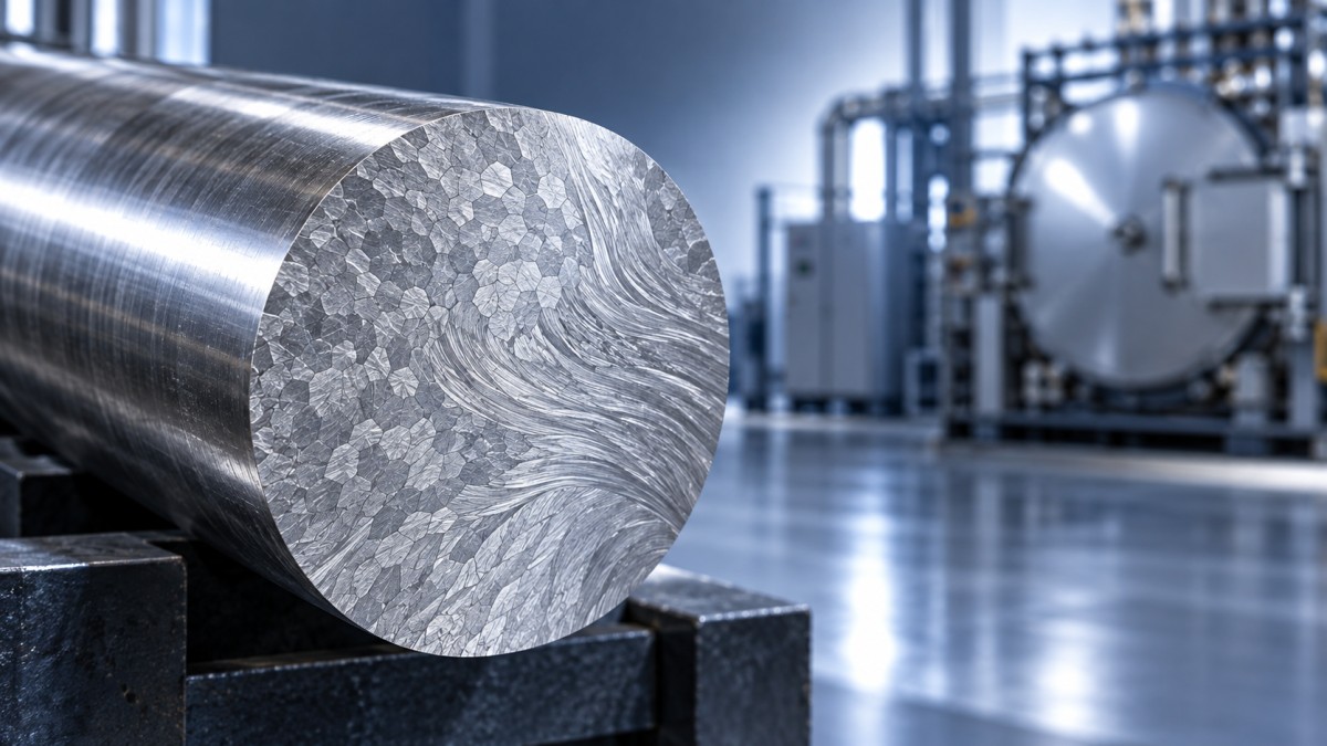
Metal grains are regions with different crystallographic orientations. Their boundaries interrupt slip movement within the material. In many alloy systems, a relatively fine and uniform grain structure can improve resistance to fatigue-crack initiation because deformation is distributed across more boundaries instead of concentrating in a few large grains.
That does not mean “finer is always better.” At elevated temperature, grain boundaries can become locations for creep damage, oxidation-assisted attack, or boundary sliding. High-temperature nickel-based alloys may therefore be processed toward a grain condition that balances room-temperature fatigue behavior with creep strength and thermal stability. The right structure for a rotating component at ambient temperature is not automatically the right one for a combustion-zone part operating for long periods under heat.
Coarse grains are especially worth attention when cyclic stress is high. A large grain permits longer slip bands to develop. Where those slip bands intersect the surface, a small persistent deformation feature may form and become a crack origin. In a polished laboratory specimen this mechanism can be clear; in an industrial part it often interacts with machining marks, corrosion pits, or local stress concentration at threads and keyways.
Uniformity Matters More Than an Average Grain-Size Number
An average grain-size result can conceal a serious local issue. Mixed grain size, abnormal grain growth, and banded microstructures may create areas that respond differently to cyclic loading. A bar may look acceptable on a limited metallographic field while containing a coarser region closer to the centerline or near a change in section. This is one reason sampling location should be agreed before inspection, particularly for large-diameter stock.
For fatigue-critical work, quality personnel should ask whether the grain condition is consistent from surface to core and from one heat-treatment lot to the next. The question is not simply “What is the grain size?” but “Where was it measured, how representative is it, and does it match the intended forging or machining route?”
Directionality also deserves attention. Hot rolling and forging elongate grains, inclusions, and segregation patterns along the working direction. When the service load is parallel to the bar axis, that orientation may behave differently from a transverse loading condition. A part machined from an Alloy Bar should therefore be reviewed in the actual loading direction, not only against a generic material description.
Inclusions and Segregation Often Start the Real Problem
Grain structure is inseparable from cleanliness. Non-metallic inclusions, carbide clusters, porosity, and chemical segregation create local stiffness and strength differences. Under repeated stress, these discontinuities can raise microscopic stress concentration and give a crack an easier starting point. The risk becomes more pronounced when the component experiences vibration, pressure pulsation, thermal cycling, or corrosive media.
For nickel-based, iron-based, titanium, cobalt-containing, and corrosion-resistant materials, the exact concern changes with alloy chemistry and manufacturing route. Carbides may be deliberately controlled for high-temperature strength, for example, but their morphology and distribution still matter. A coarse or continuous boundary network may not behave like finely dispersed strengthening particles. This distinction is easy to lose when procurement focuses only on nominal alloy grade.
The practical lesson is straightforward: a chemical certificate confirms composition within the agreed range, but it does not by itself demonstrate a fatigue-ready microstructure. Metallographic review, process traceability, and appropriate non-destructive examination each address different parts of the risk.
Heat Treatment Can Improve Fatigue Performance—or Undo Good Processing
Solution treatment, annealing, aging, stress relief, cooling rate, and subsequent straightening all affect the final condition of an alloy bar. A controlled heat-treatment cycle can dissolve undesirable phases, refine or stabilize precipitate distributions, reduce residual stress, and establish properties suited to the application. An unsuitable cycle may promote excessive grain growth, incomplete dissolution, sensitization in susceptible alloys, or uneven properties through the section.
Residual stress deserves special caution. Surface compressive residual stress can delay fatigue-crack initiation, while tensile residual stress can have the opposite effect. However, machining, grinding burns, welding, local heating, and aggressive straightening can alter that condition after the mill heat treatment. A good bar can therefore become a poor fatigue component through downstream processing.
When failure consequences are high, review the complete route: melt practice, reduction ratio where relevant, heat treatment, machining allowance, final surface condition, and any thermal exposure expected in service. Looking only at the supplied bar certificate is rarely enough.
What to Check Before Releasing Material for Cyclic Service
A focused inspection plan is usually more useful than a long generic checklist. For an Alloy Bar intended for fatigue-sensitive components, the following points tend to provide meaningful evidence:
- Confirm the required alloy grade, product form, condition, dimensions, and heat or lot traceability.
- Define the critical loading direction and ensure metallographic sampling reflects that orientation.
- Review grain size for uniformity, not merely compliance with a single average value.
- Check for surface decarburization, oxide scale, laps, seams, grinding damage, and other defects that can dominate crack initiation.
- Match non-destructive testing methods and acceptance criteria to the component’s failure consequence and final machining depth.
- Assess whether the specified heat treatment remains suitable after welding, bending, machining, or high-temperature exposure.
If fatigue testing is required, the test condition needs to resemble the actual risk as closely as practical. Stress ratio, surface condition, test temperature, environment, notch sensitivity, and sample orientation can substantially change the result. A fatigue value from a polished axial specimen should not be assumed to represent a threaded, transverse-loaded, corrosion-exposed part.
High-Temperature Applications Need a Different Conversation
In turbines, boilers, reactors, steam systems, and chemical-processing equipment, fatigue may combine with temperature gradients, oxidation, creep, and corrosive deposits. Here, grain structure must be evaluated alongside phase stability and environmental resistance. Nickel-, chromium-, molybdenum-, cobalt-, and iron-containing high-temperature alloys are selected precisely because they can retain strength and oxidation resistance under demanding conditions, but their processing window is not interchangeable.
The same metallurgical discipline applies when bar stock is converted into adjacent pressure or fluid-handling components. For applications involving Inconel, Hastelloy, Incoloy, or Waspaloy systems, High-Temperature Alloy Tubes may be specified for service from 650°C to 1000°C, depending on alloy selection and actual operating conditions. Tube dimensions, wall thickness, joining processes, and thermal cycling should be reviewed as part of the assembly-level fatigue assessment rather than treated as separate purchasing decisions.
Shandong Titanium Nickel Special Steel Co., Ltd. works with nickel-based and iron-based special alloys as well as corrosion-resistant alloys, precision alloys, titanium, zirconium, copper-nickel, Monel, INCONEL, INCOLOY, Hastelloy, hafnium, and other material families. For this broad material range, the useful starting point is not a universal grain-size target. It is a clear statement of service temperature, cyclic load, environment, part geometry, and allowable inspection evidence.
A Material Release Decision Should Follow the Failure Mode
The most reliable fatigue decisions connect microstructure to the actual component failure mode. If cracks are expected to begin at a machined surface, surface integrity may deserve more scrutiny than bulk grain size. If the part is thick, highly loaded, and exposed to elevated temperature, core structure, segregation, and heat-treatment penetration become more influential. If corrosion fatigue is plausible, pits and environmental compatibility may control the outcome before the nominal fatigue limit is reached.
Grain structure is therefore not a box to tick on an inspection report. It is evidence of how the material was processed and a clue to how it may respond when repeated loading starts to expose its weakest local feature. For safety-critical alloy components, that evidence should be reviewed before the first crack has a chance to become a failure investigation.
